Project
Electric Moped
A ground-up electric vehicle build — the utility of a moped with the design of a motorcycle. Currently in progress.
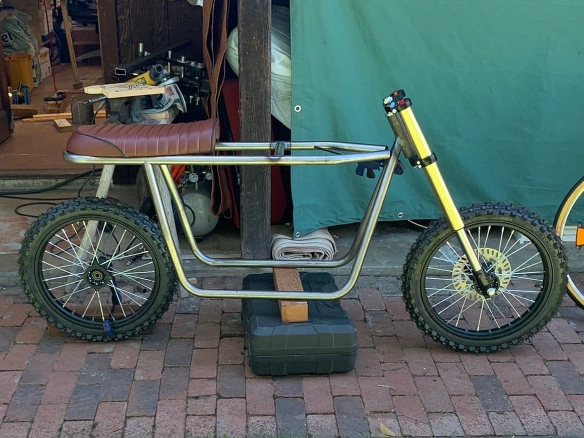
Work in progress
Goals:
- Build an EV with the utility of a moped, but the design of a motorcycle
- Integrate CAD, FEA, and other engineering skills I learned in college
- Emphasize DFM, both mechanical and electrical
- Enjoy the process and the final product
The Planning Stage
Design planning
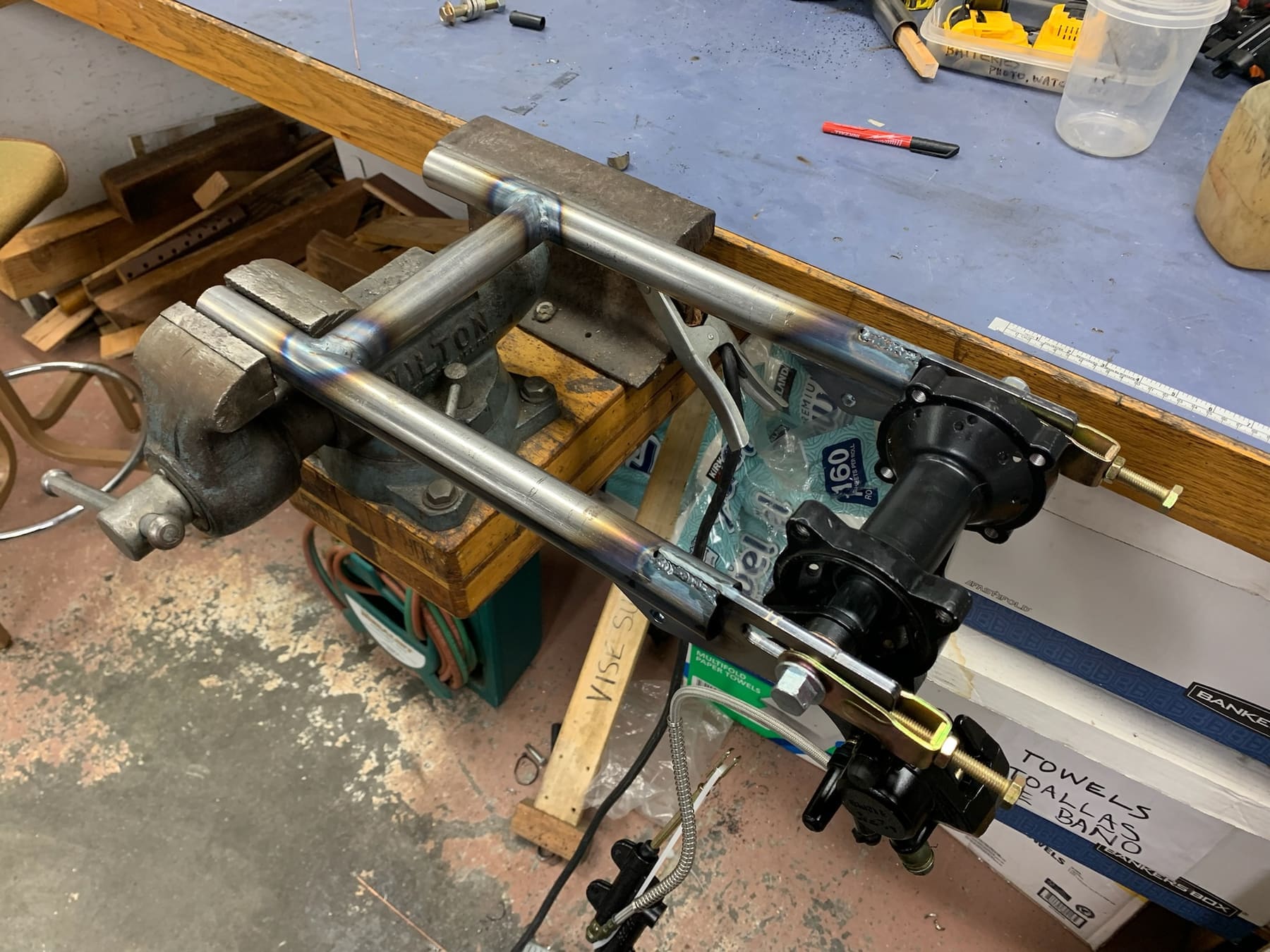
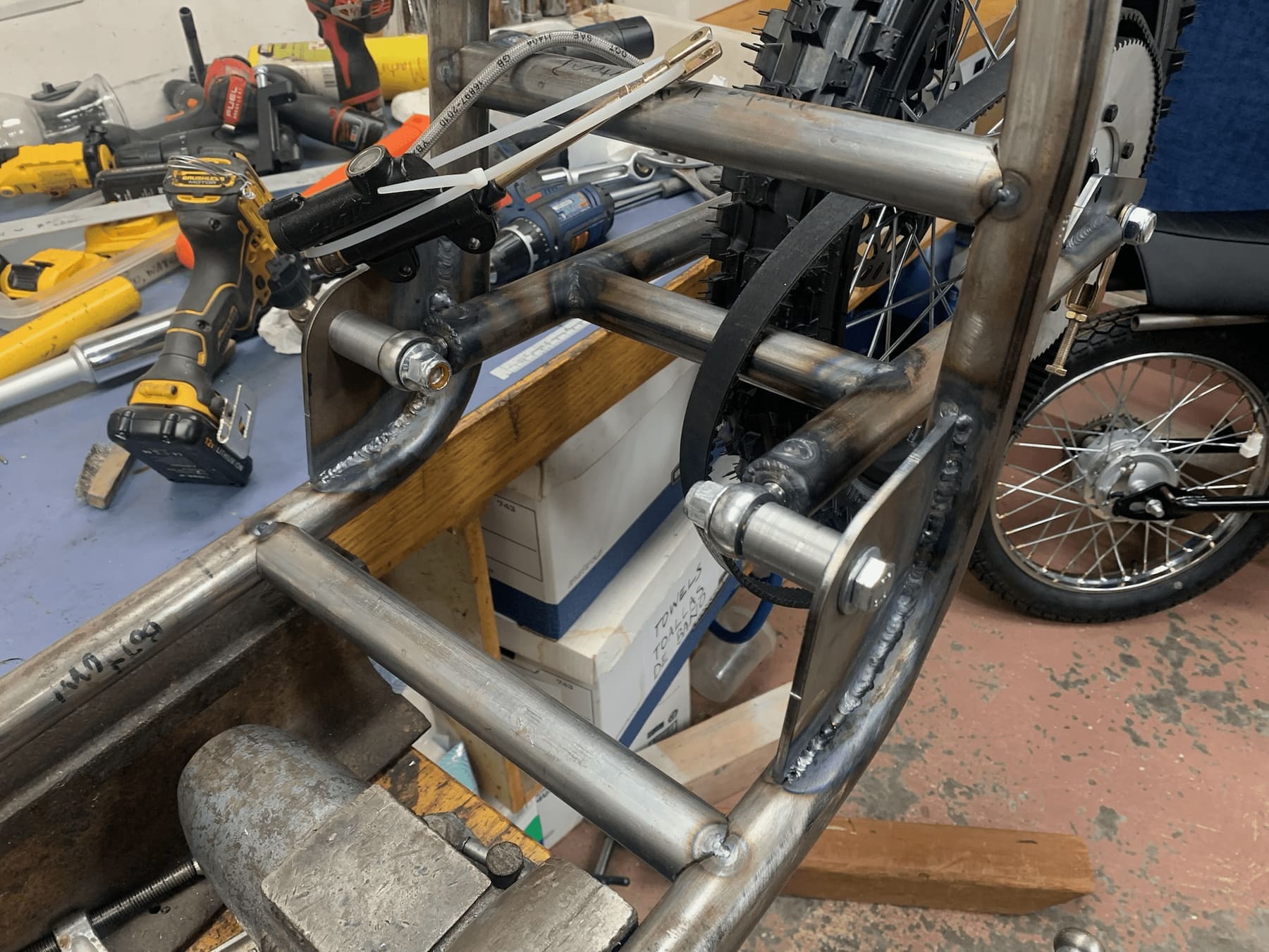
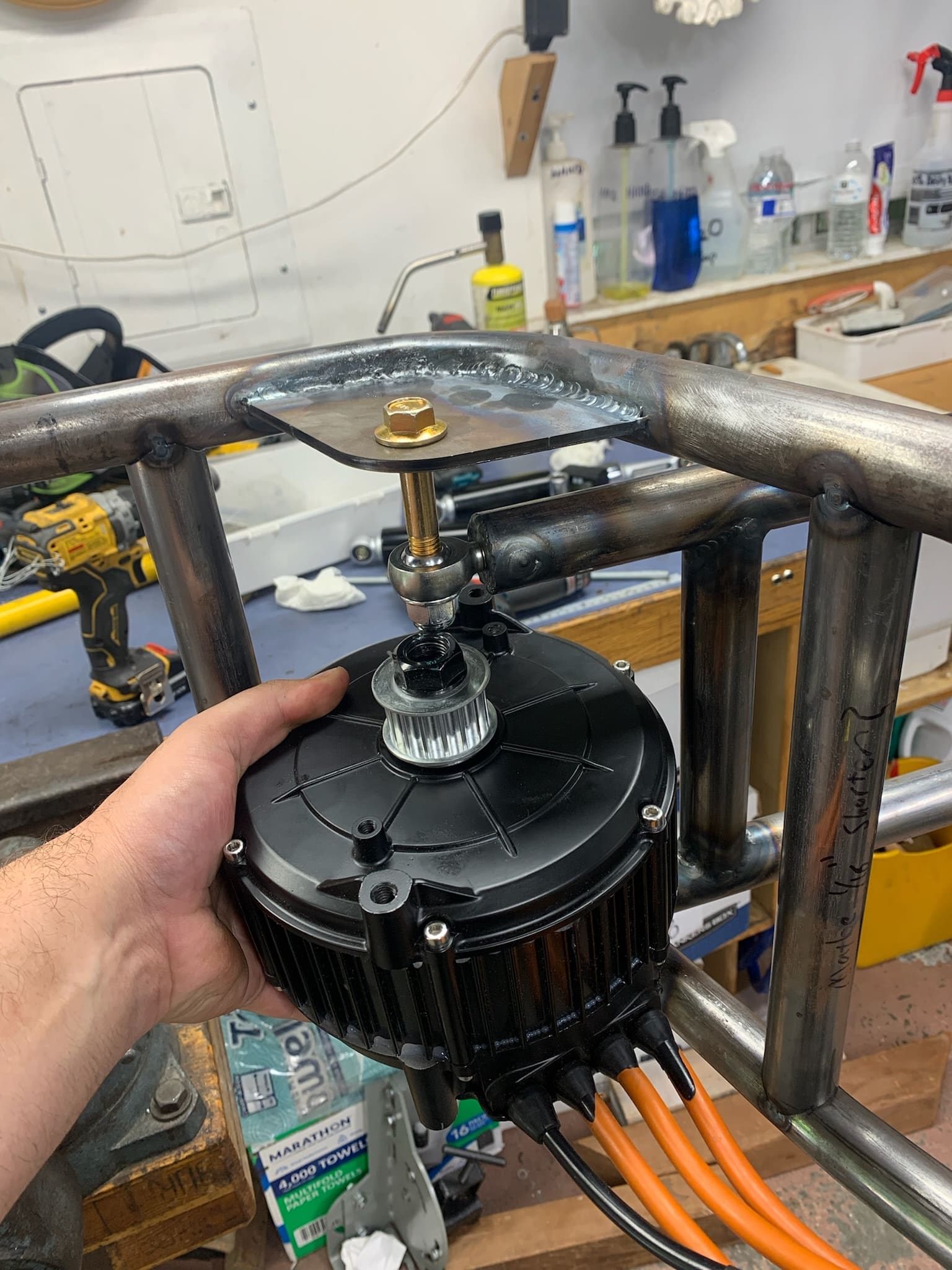
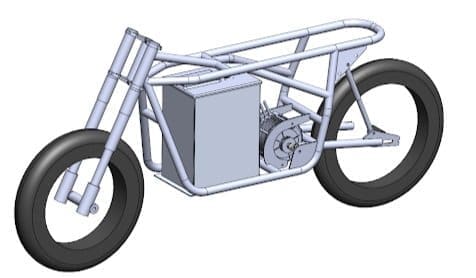
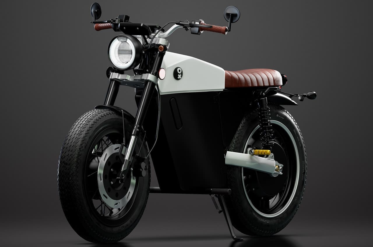
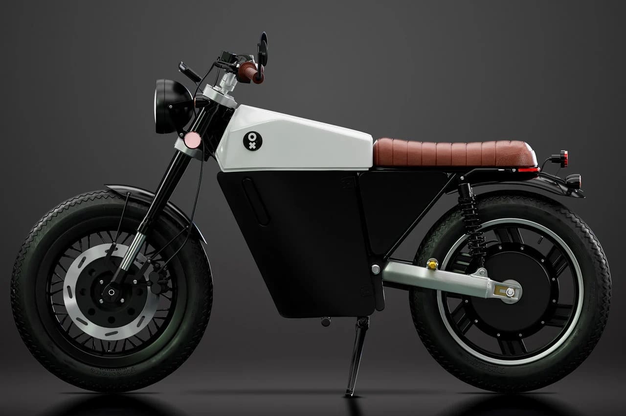
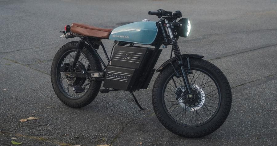
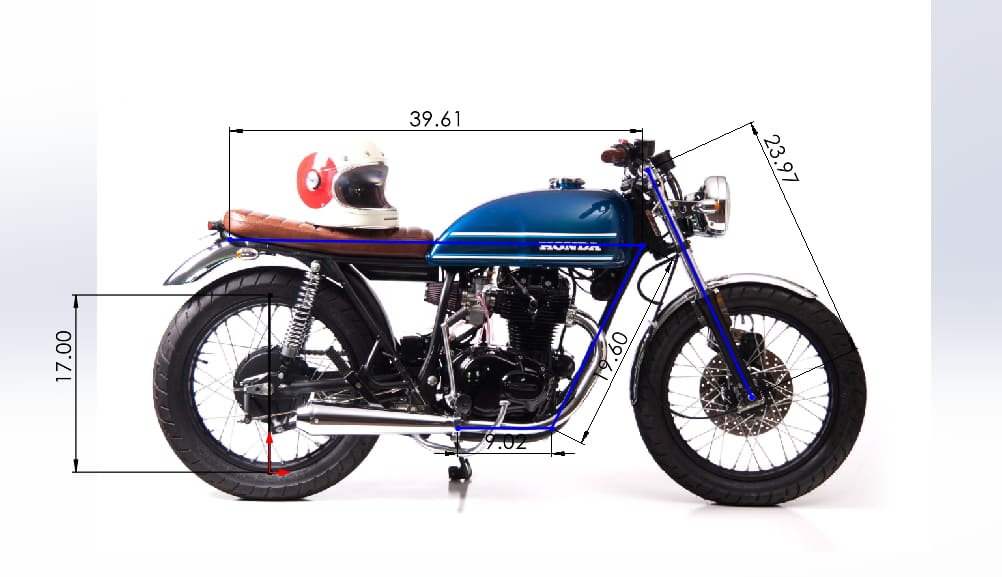
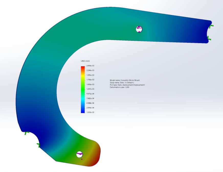
I spent a lot of time looking at mopeds and motorcycles to figure out what I wanted to build, and landed on a modern take on 1970s bikes. I also decided to use a belt drive, mainly to reduce noise — which meant the motor and swingarm needed to be coaxial.
Design for Manufacturing: Battery
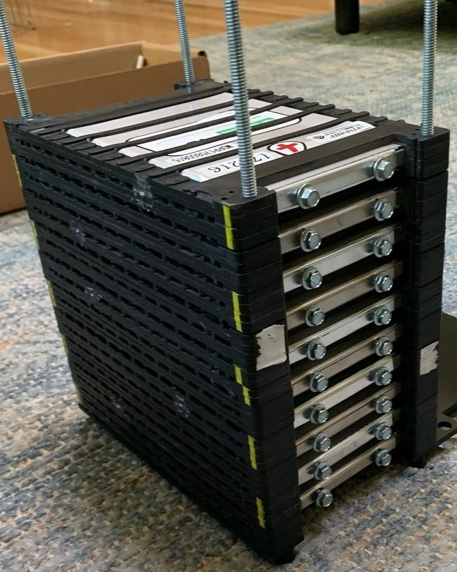
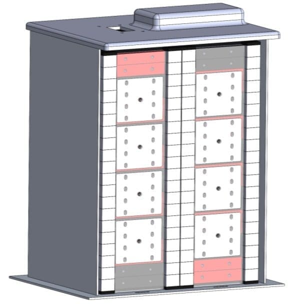
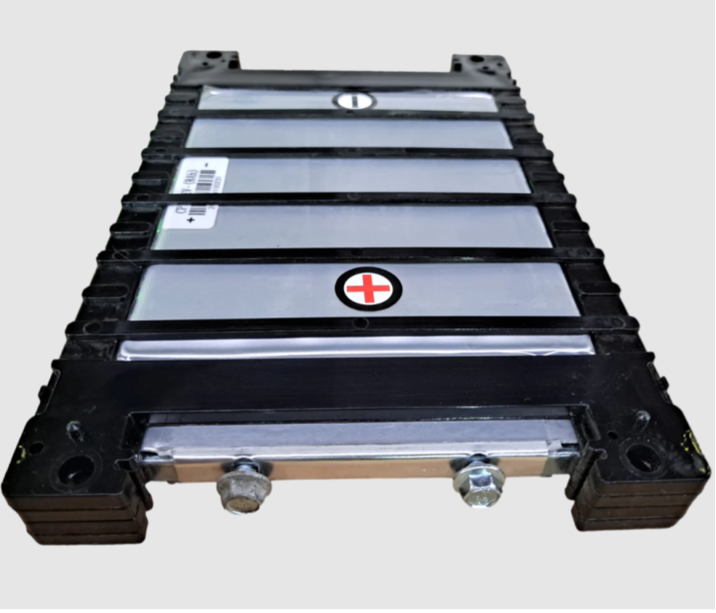
I had two main goals for the battery pack: make sure it wasn't the limiting factor, and avoid unreliable electrical connections like spot welds or wire bonds.
I found pouch cells with threaded tabs and tested them on the bench I'd built for BOLT — each cell can put out my burst current on its own, and I'm running four in parallel. That means even a full-throttle draw for the pack's entire lifetime stays below its temperature limit, which meant I could seal the pack without worrying much about cooling.
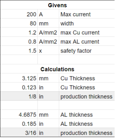
I designed bolt-on busbars (laser cut) for the series and parallel connections. I'd originally planned to use copper, but switched to aluminum and increased the thickness accordingly once I realized copper was outside budget.
Design for Manufacturing: Frame
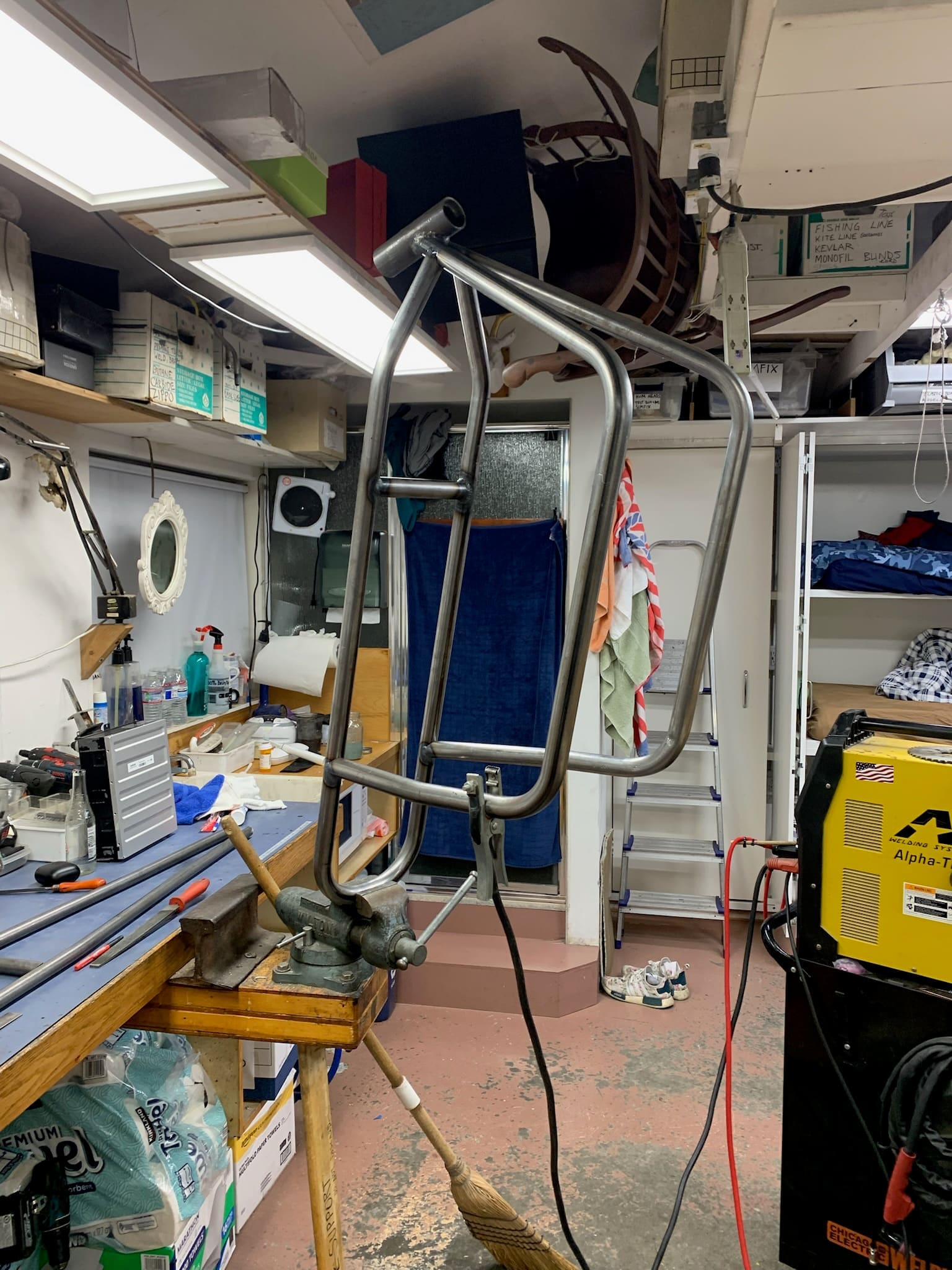
I wanted to build the frame totally ground-up so I could control every variable — the theory being that time spent on design would be saved by not needing to take a grinder to an existing frame. That was laughably wrong, but still a good decision and a good experience.
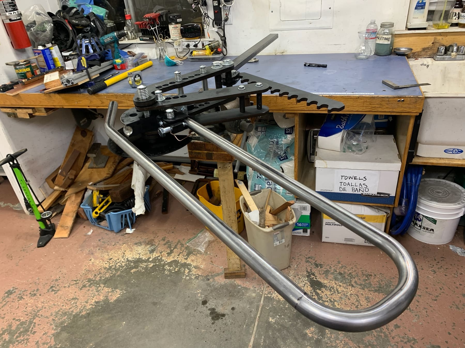
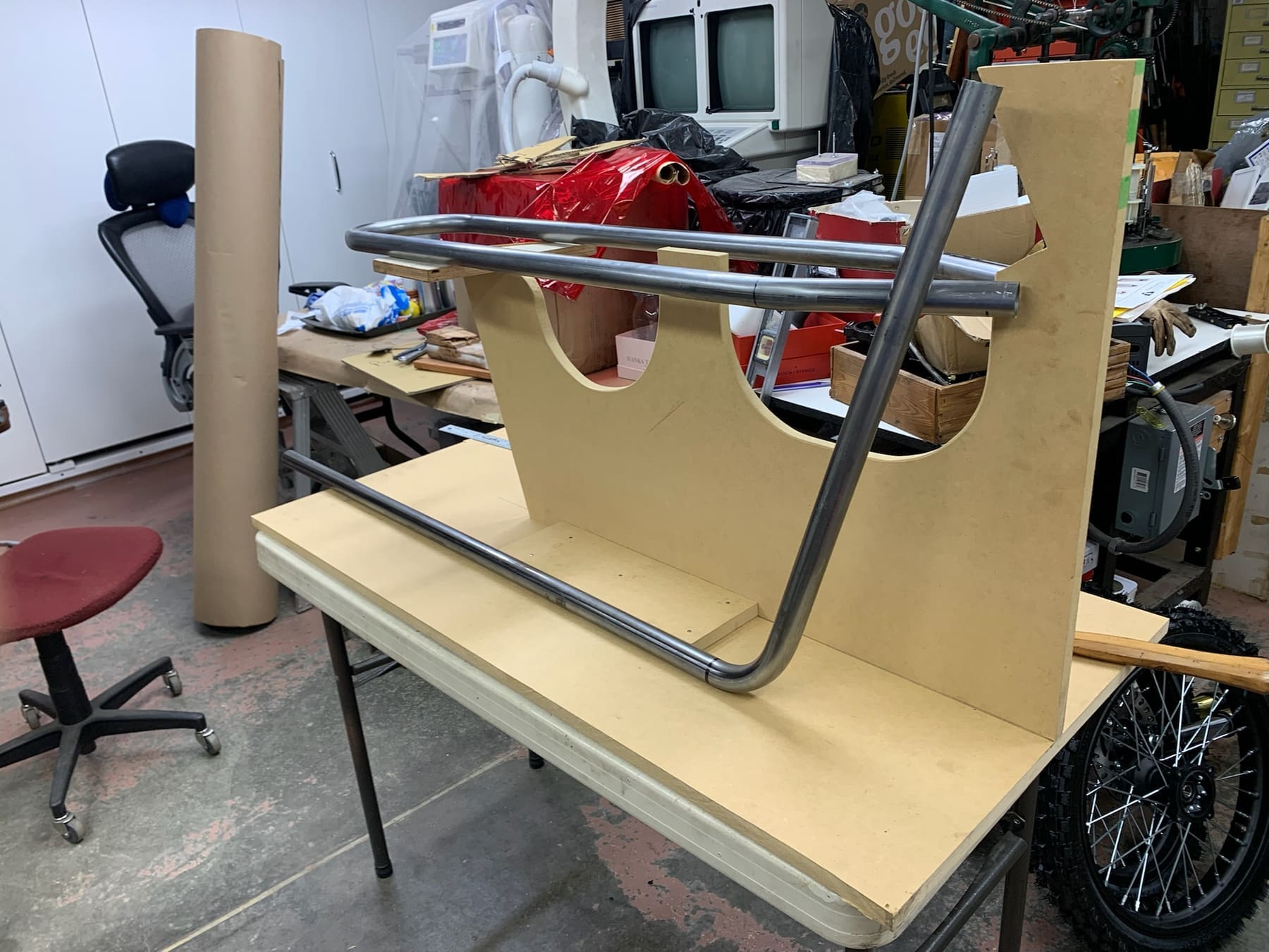
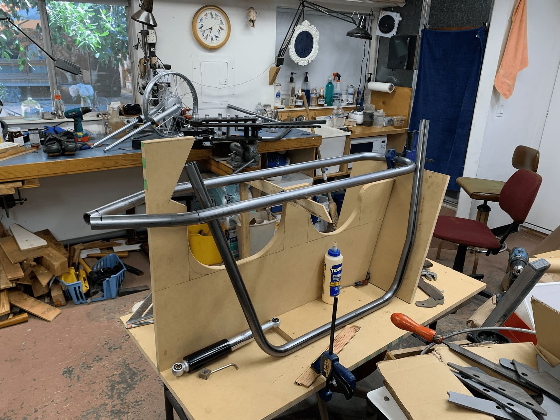
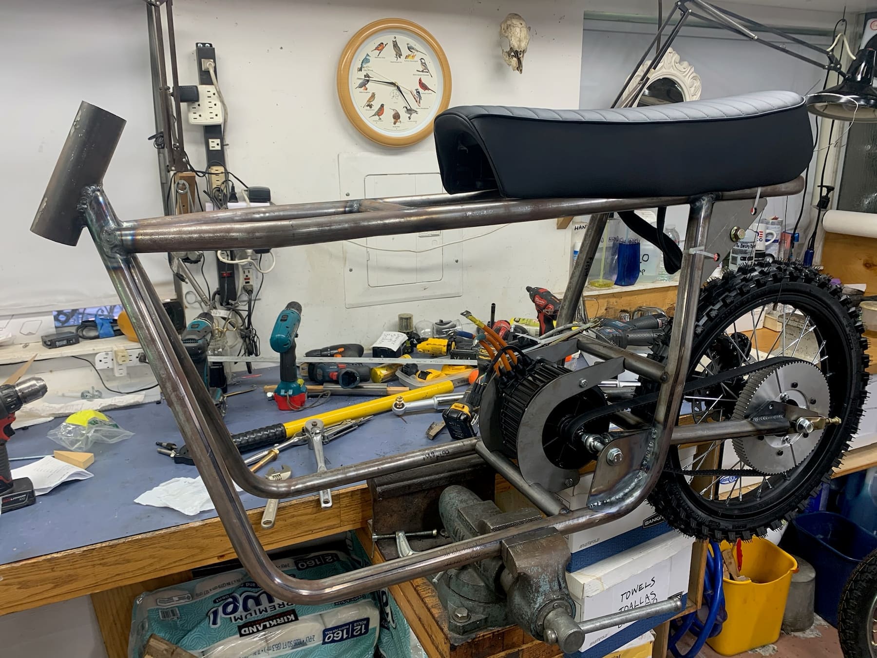
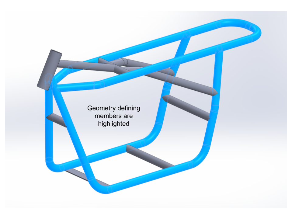
For the frame, bent tubes and sheet metal seemed like the best route. Since tight tolerances in tube bending are hard to hold, I designed the frame around three "geometry defining members" that fit into themselves and locate everything critical, then outsourced those three and handled the rest myself. That ended up being out of budget, but I still think it was the right call — the only thing I'd change is splitting the top member into two, since the bend near it makes the frame slightly too wide in hindsight.
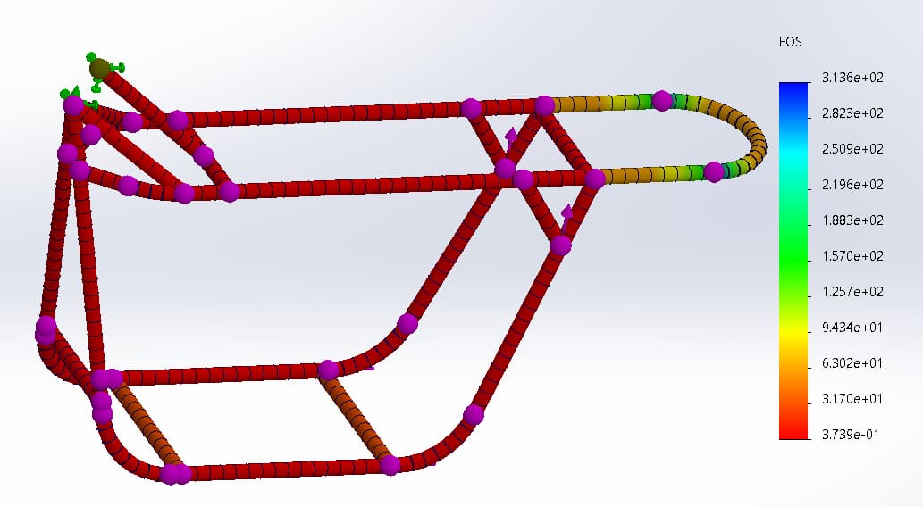
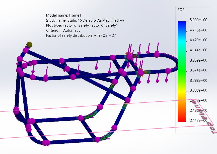
I used Solidworks FEA to evaluate the design — not fully confident in the load cases I picked, so I mostly used it as a relative metric to compare frame changes rather than an exact real-world prediction.
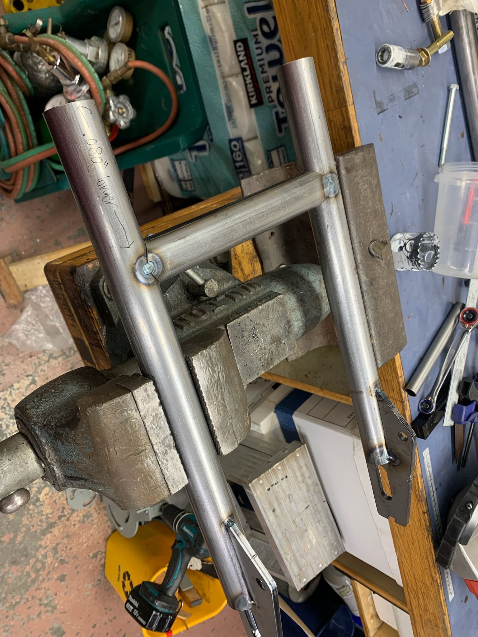
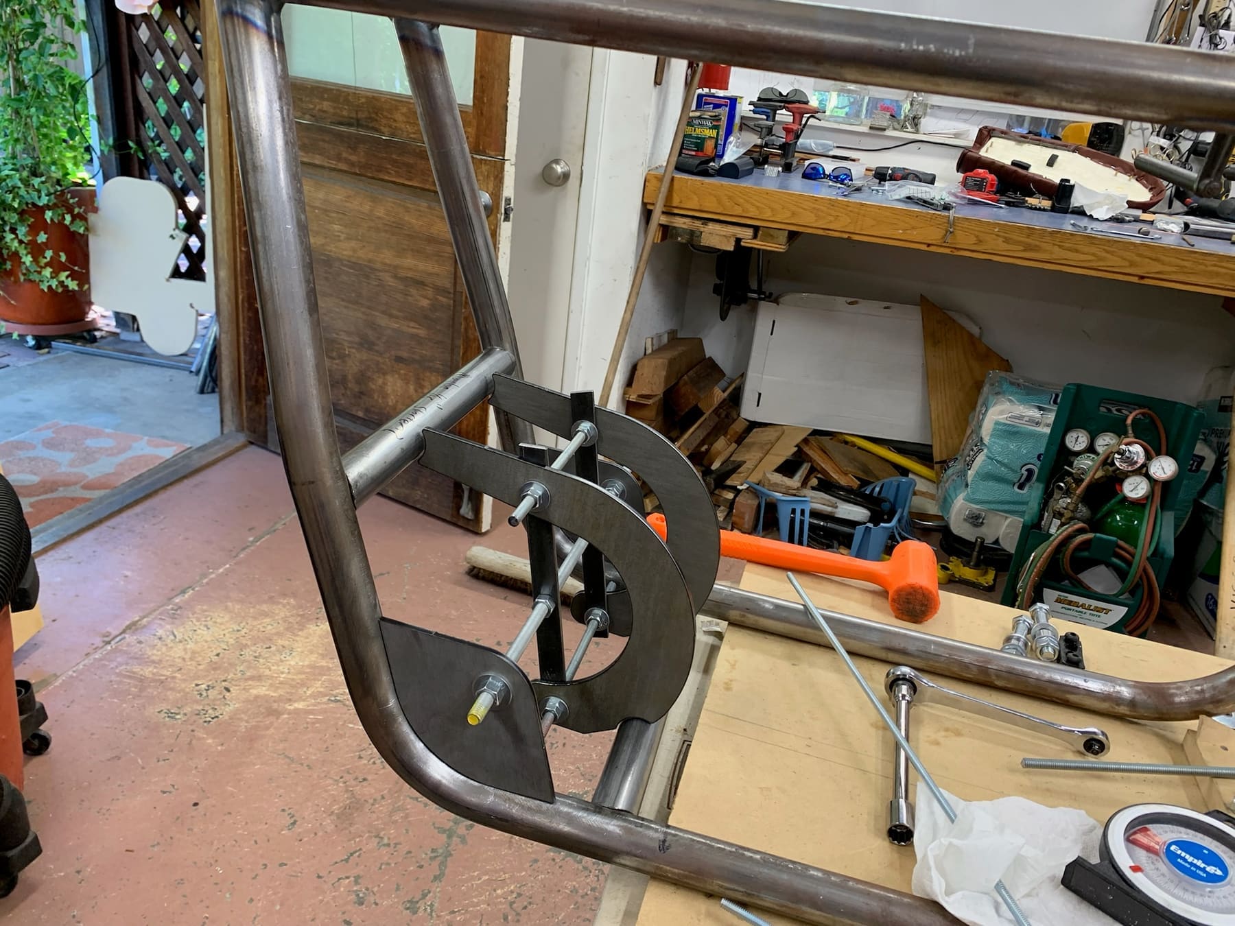
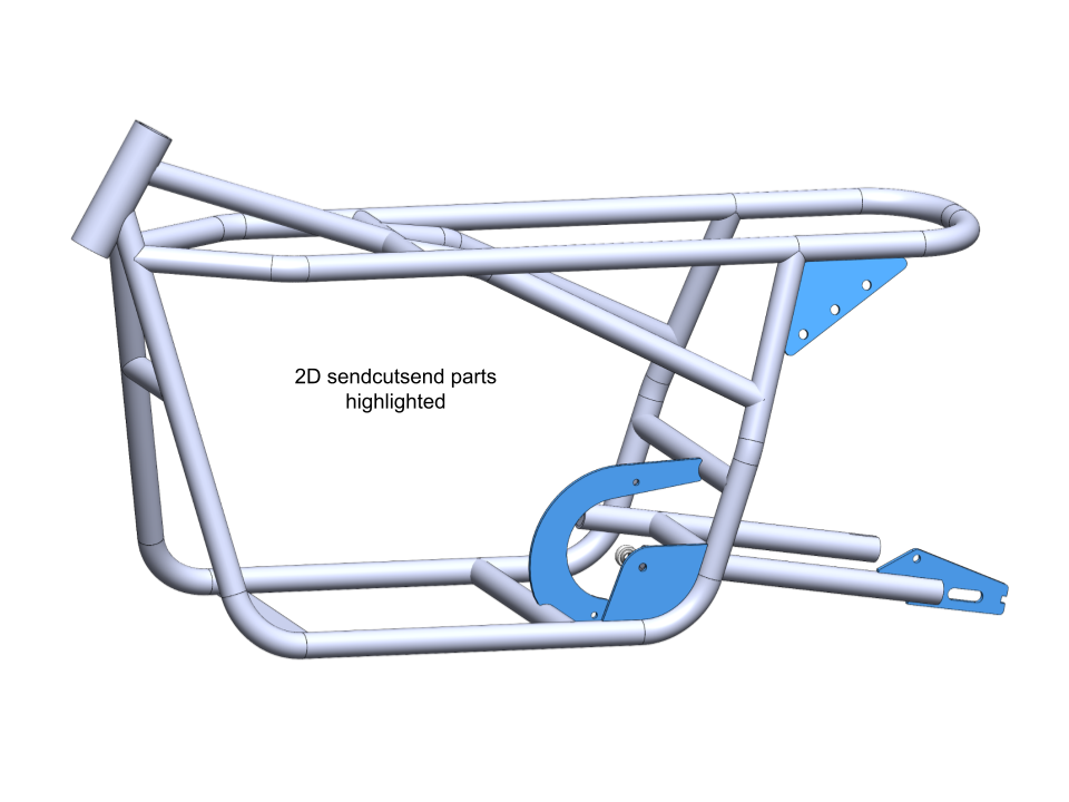
I then designed 2D plates, ordered from SendCutSend (a laser cutting service), that self-locate within the frame geometry — giving a tightly controlled interface for anything bolting to the frame.
Frame Build
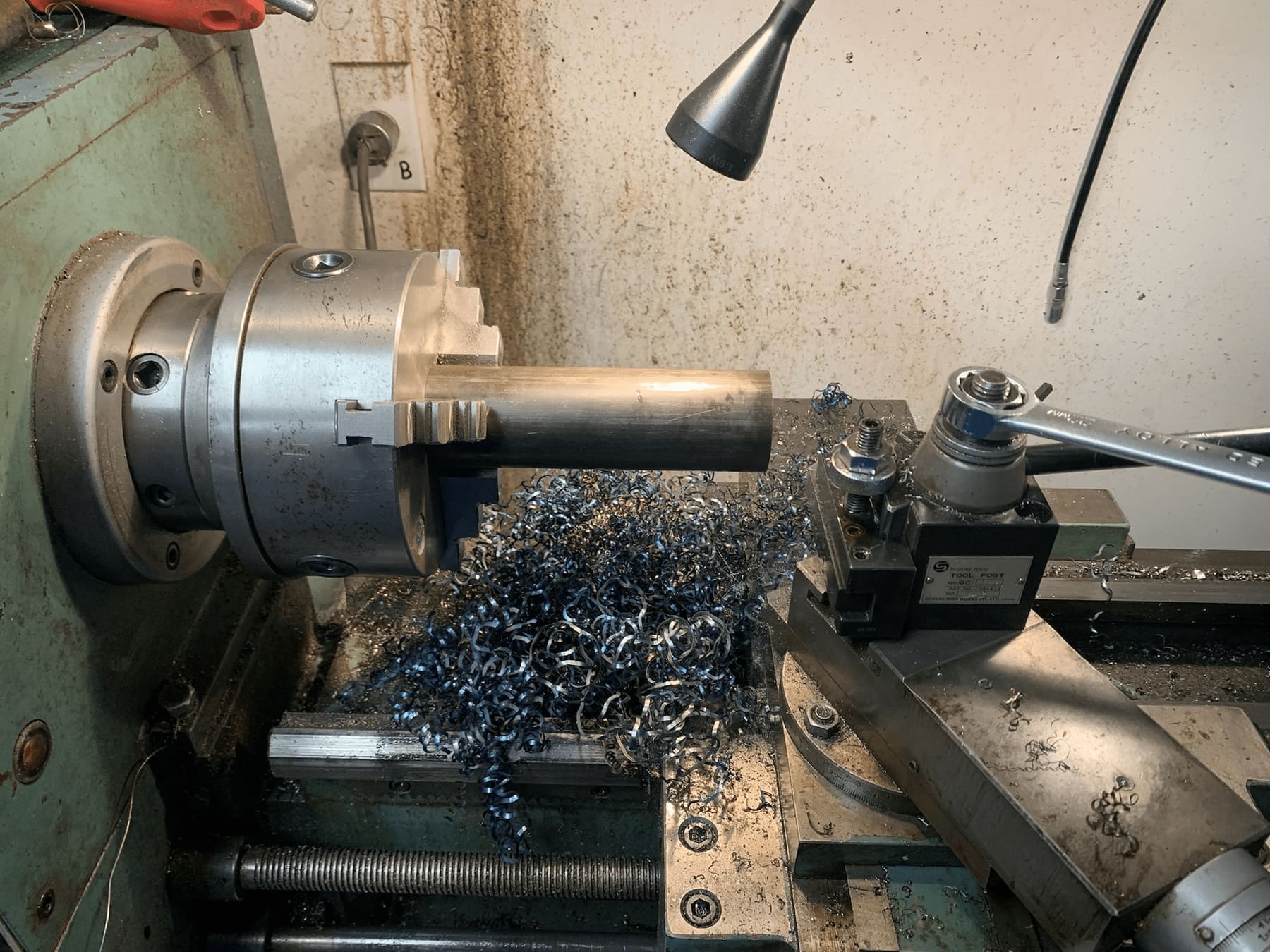
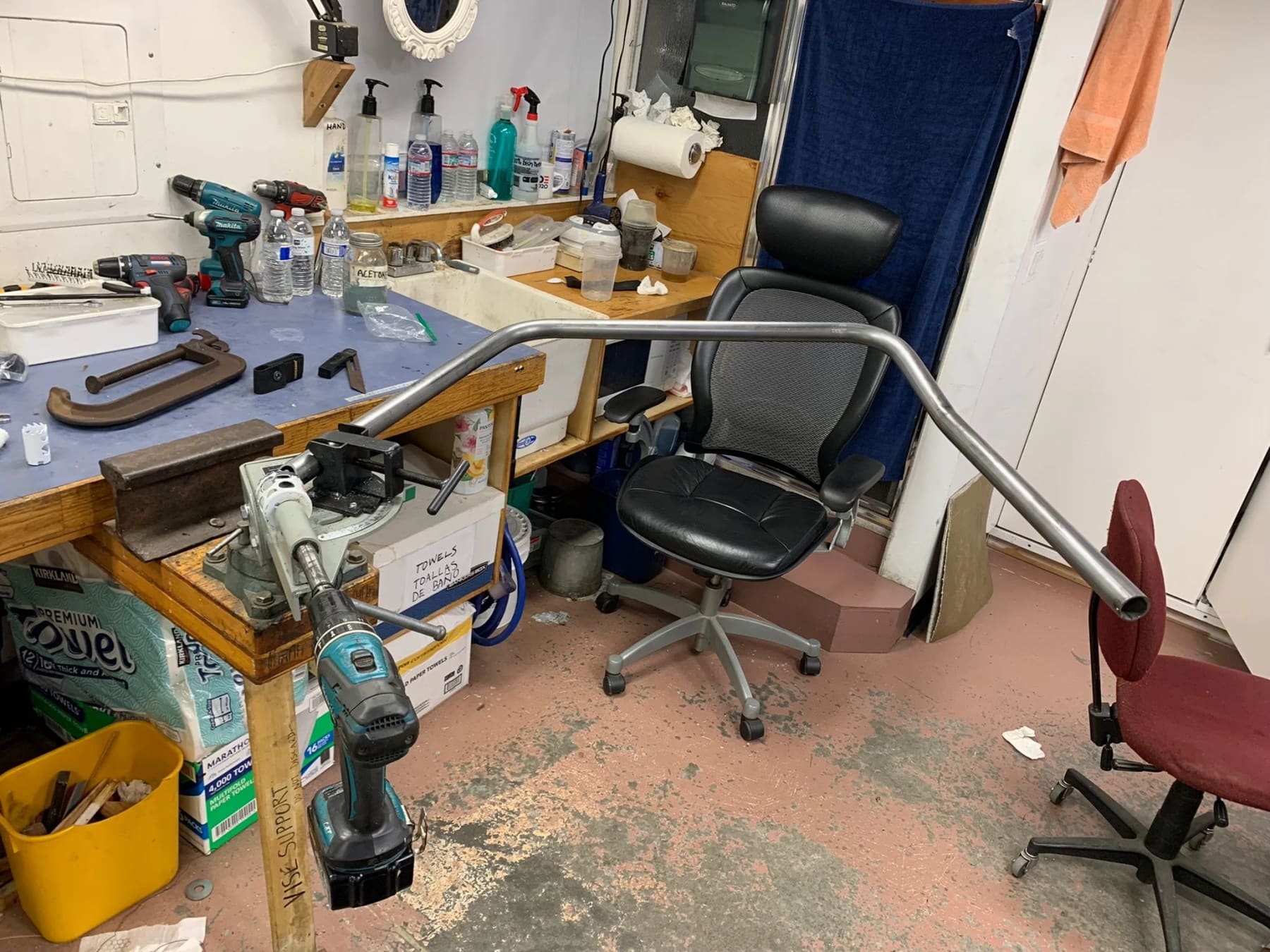
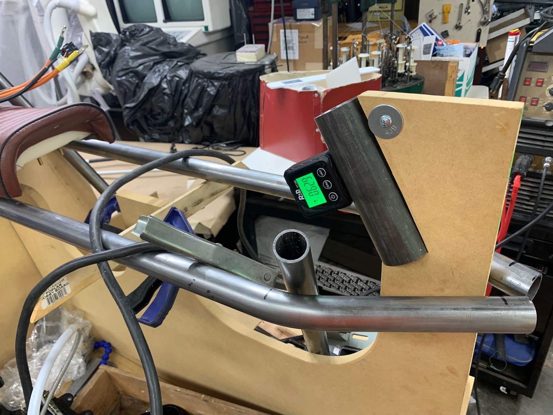
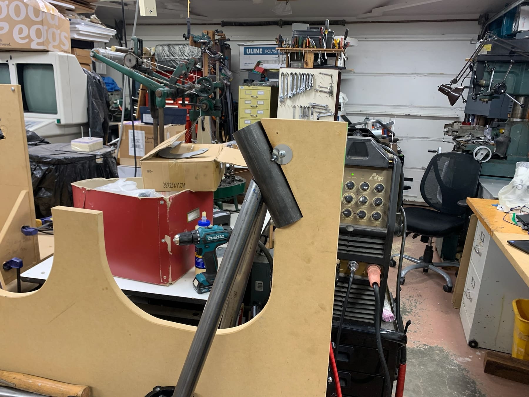
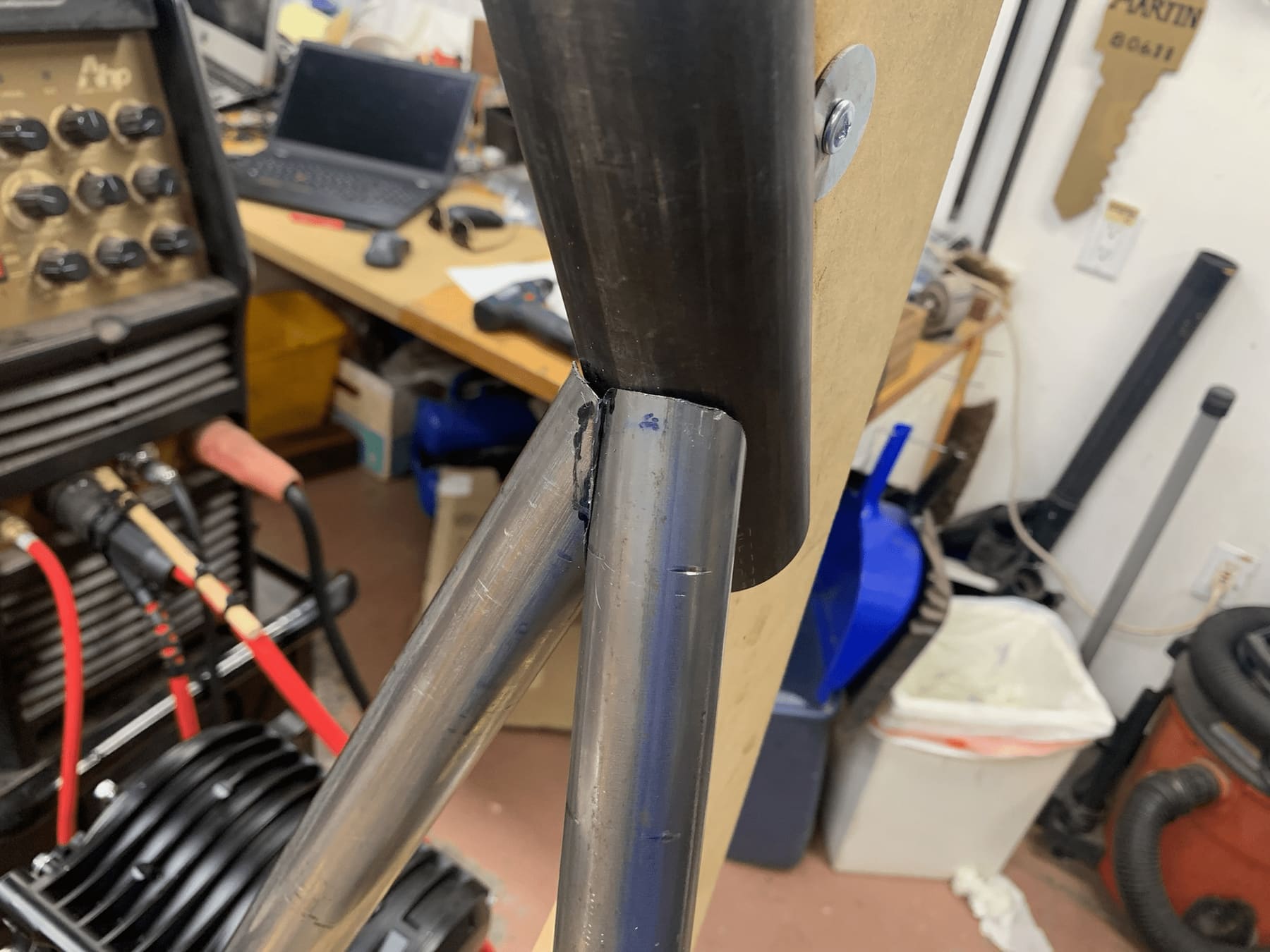
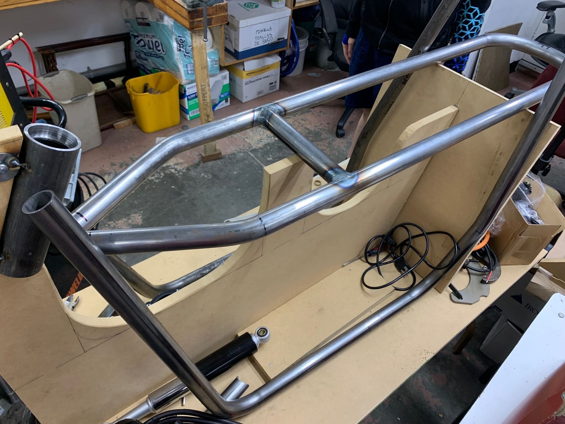
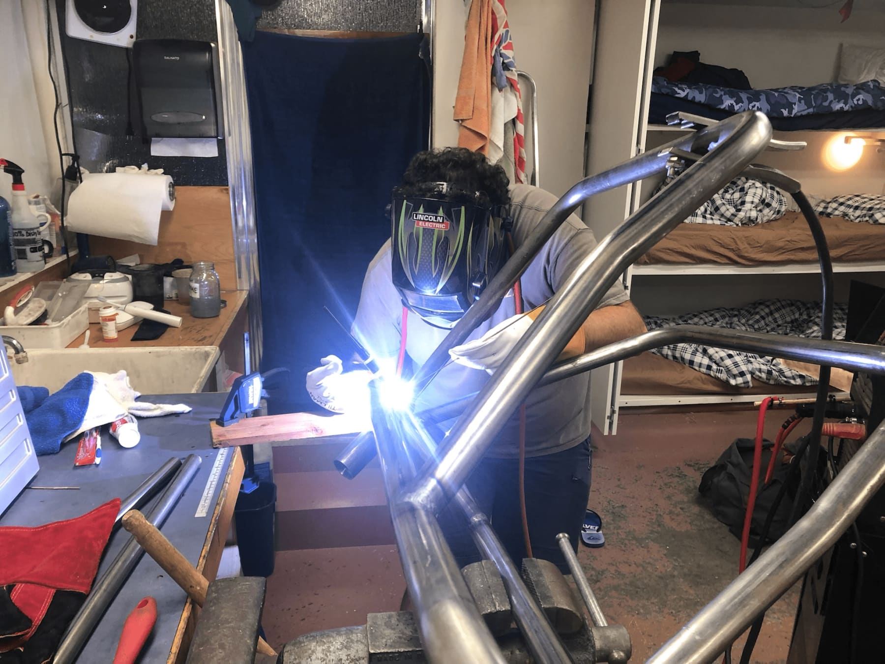
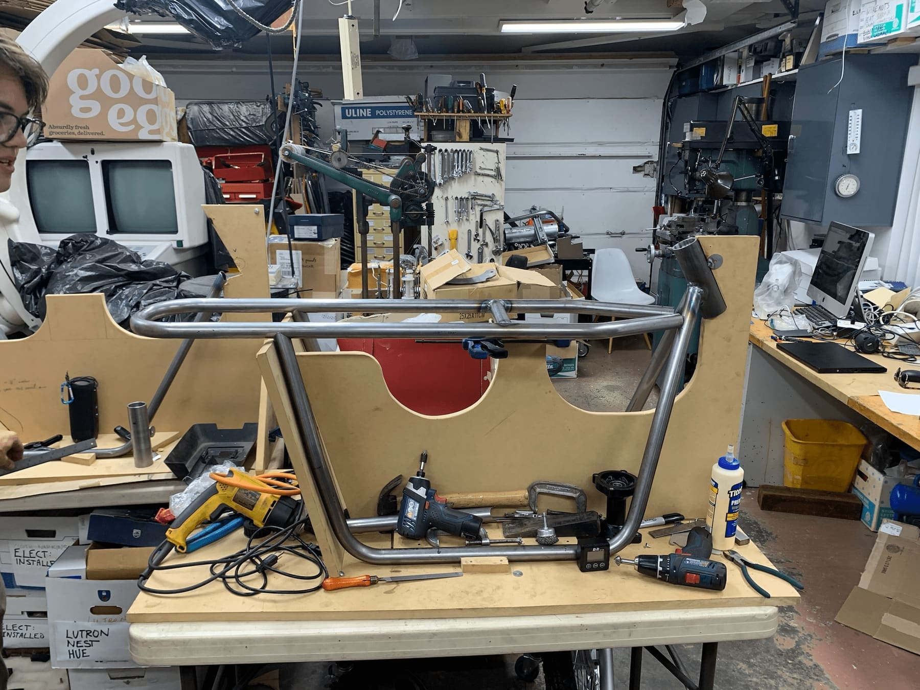
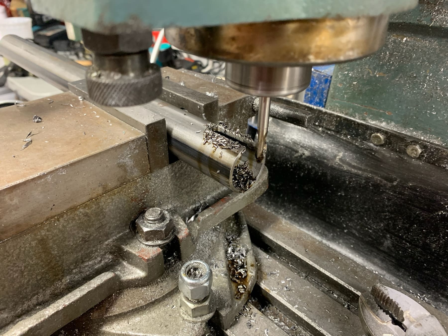
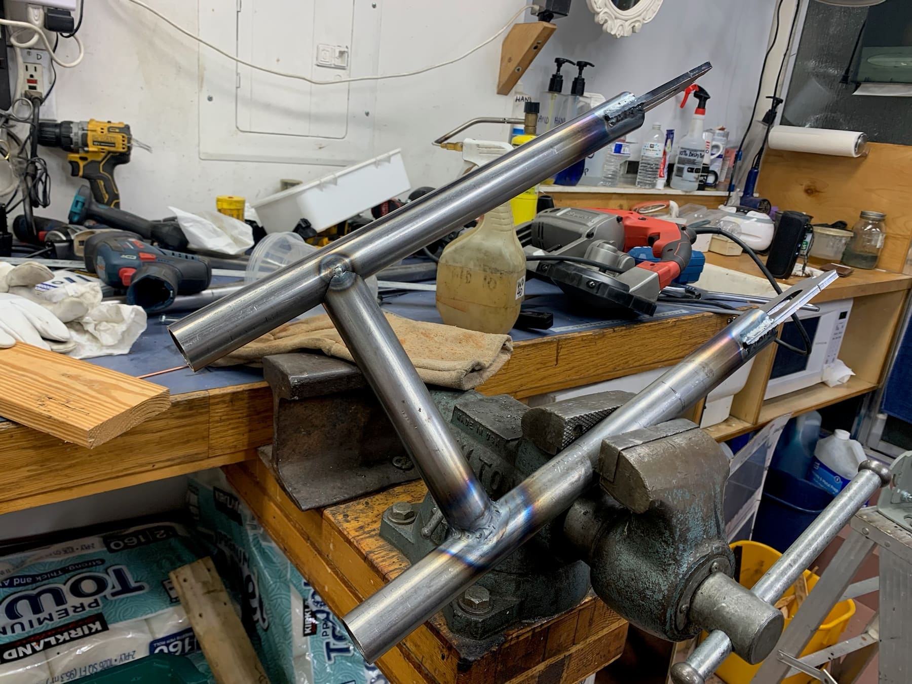
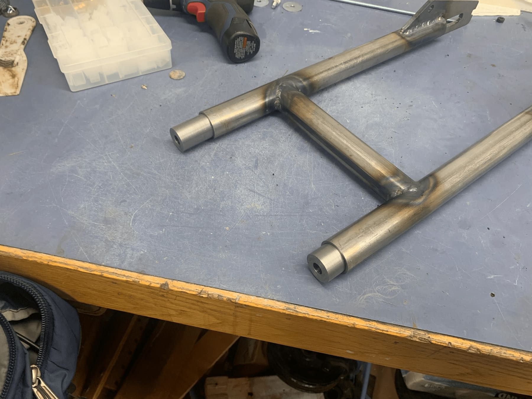
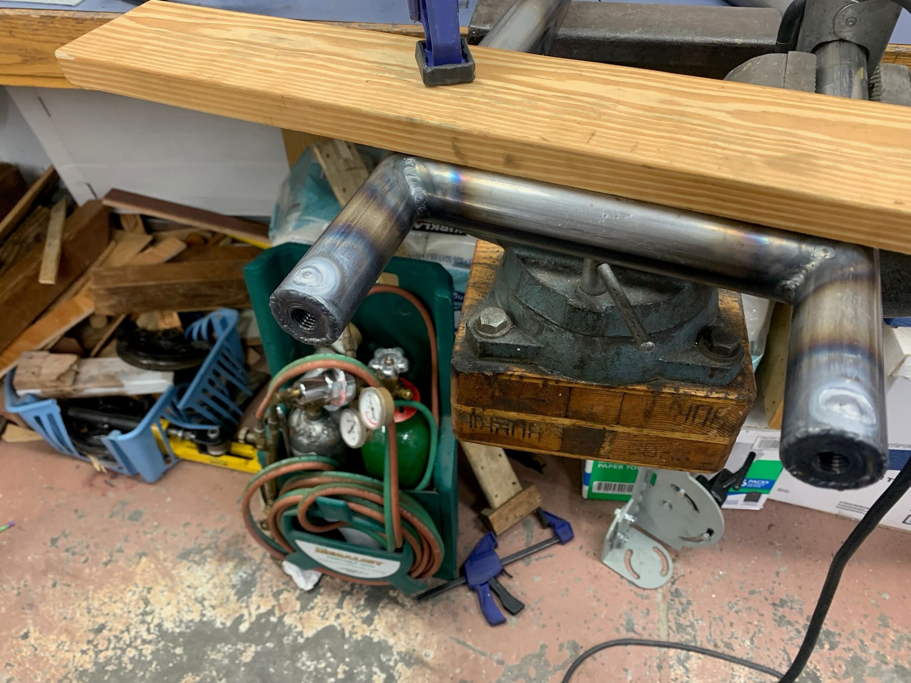
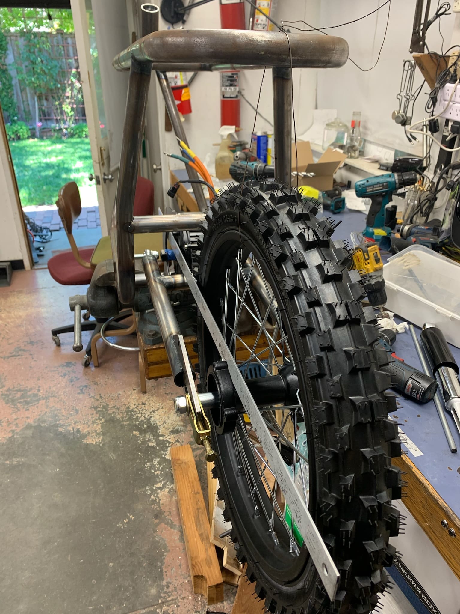
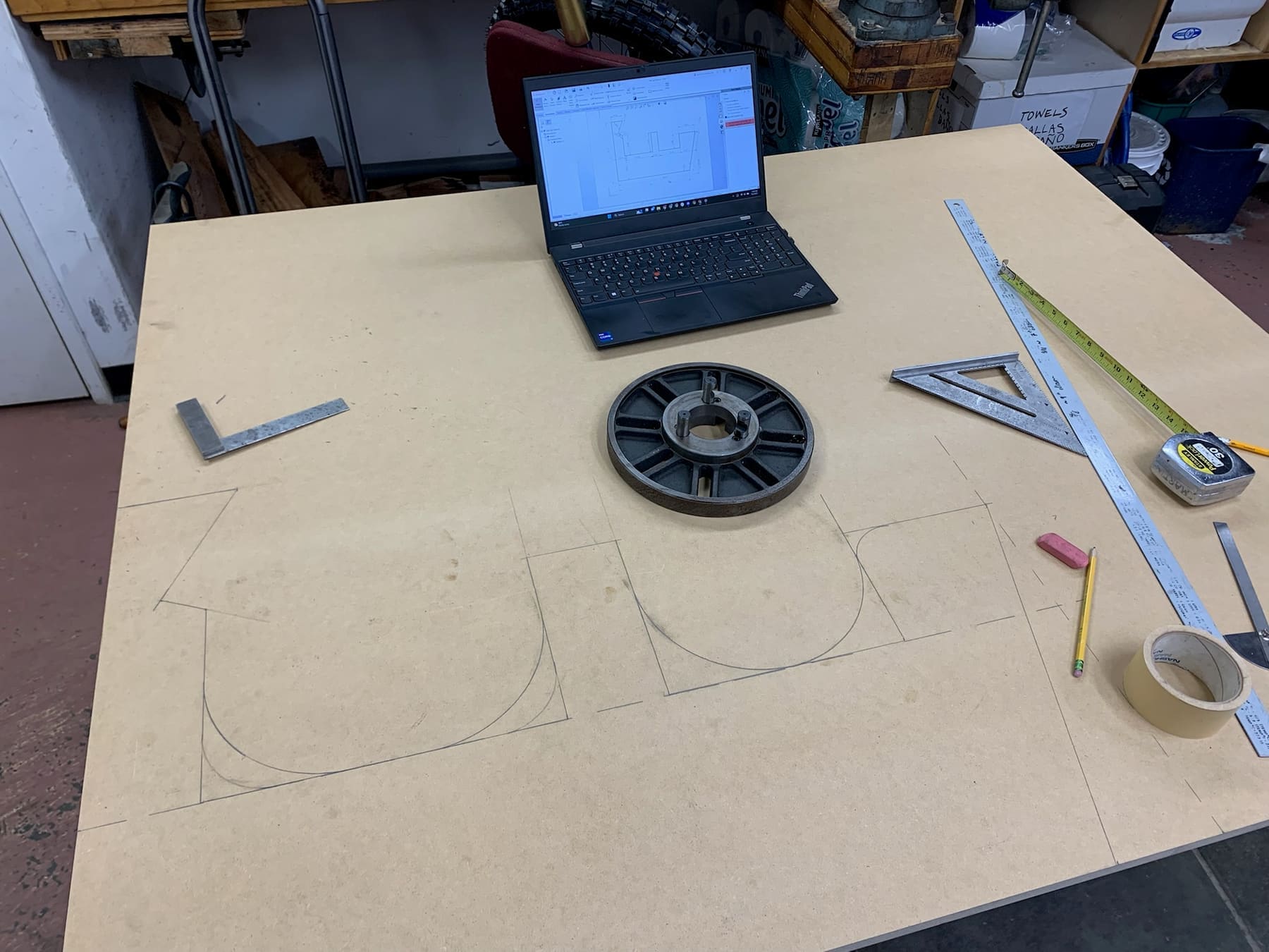
Photos of the frame build process, roughly in chronological order.