Project
BOLT at Virginia Tech
Integration lead for Virginia Tech's electric superbike race team — battery module design, test benches, and PCB work across three generations.
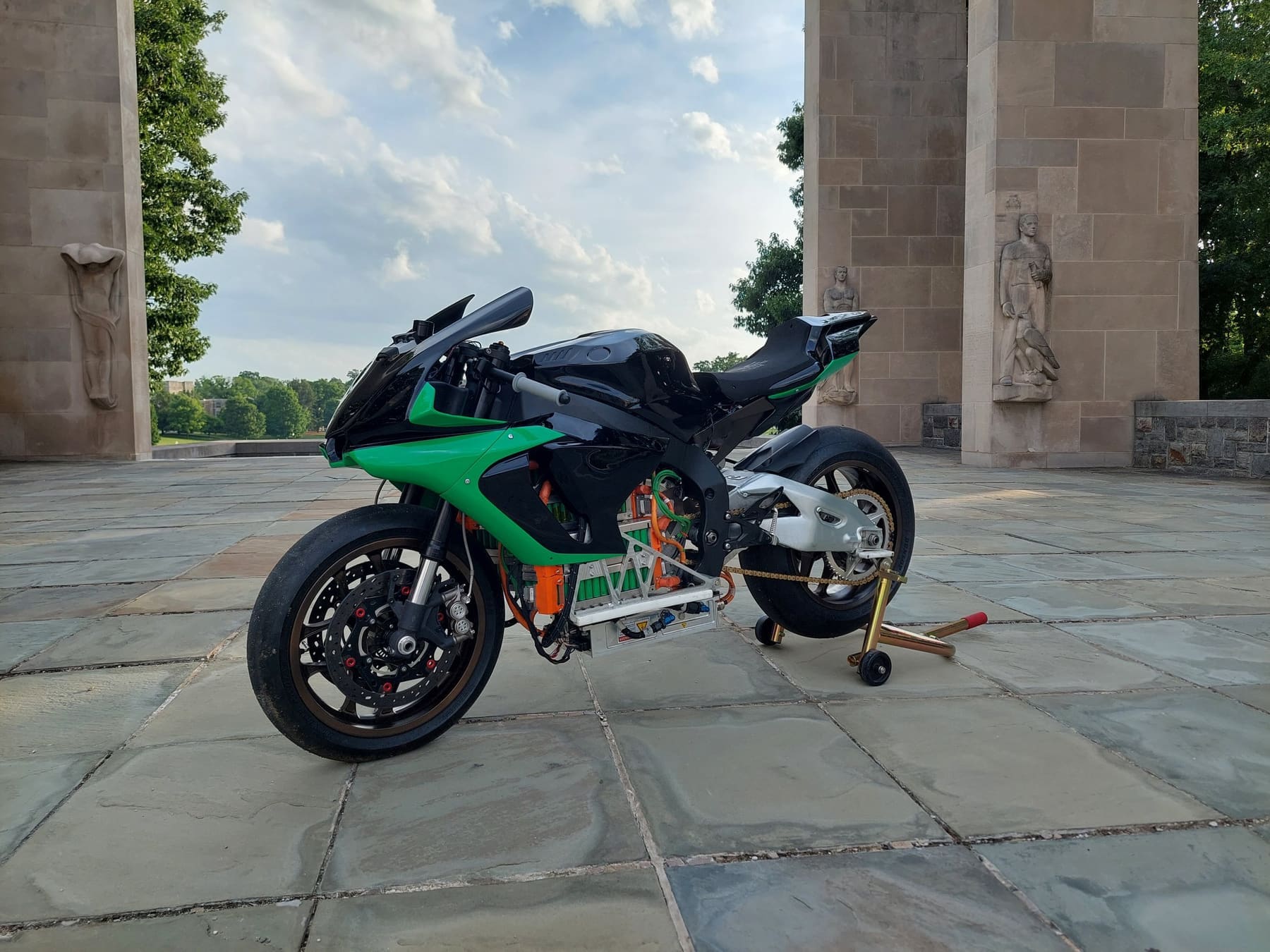
I served as integration lead for BOLT, Virginia Tech's electric superbike race team, overseeing interdisciplinary projects across the chassis, powertrain, and controls sub-teams.
The bike was engineered to match the performance of a Yamaha R1M, the top-spec race bike it was benchmarked against — roughly 600V and 160kW. More specs are available at vtbolt.com.
A few of the projects I was personally responsible for are detailed below.
Module Design
I was personally involved in the design, manufacture, and testing of three generations of battery modules.
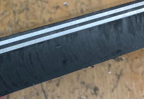
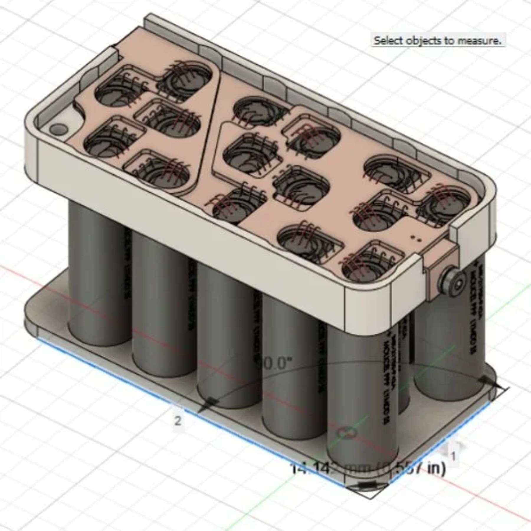
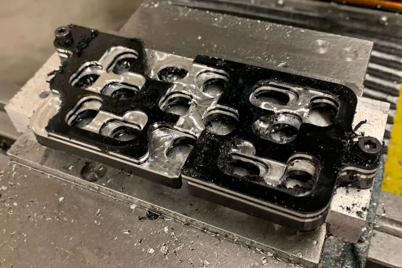
1. Laminated busbar
- Designed to have all wire bonds on the top face of the module, using shoulder bonds
- The original plan was to use special-order, large-thickness PCBs, but cost exceeded $7k — I wanted to find a way to do it in house instead
- Determined that AL1100 had the ideal tradeoff between machinability, bond strength, resistivity, and weight
- Tested 4 glues and 5 insulators (20 total options) for bond strength and machinability
- After a successful R&D process, it turned out the shoulder bonds weren't repeatable, which led to the next version
2. Top and bottom wire bonds
- After determining shoulder bonds wouldn't work, I had to pivot fast
- Redesigned and manufactured new modules within a week
- Met all design requirements, successfully pulling over 300A from a module
- During dynamometer testing, the bonds failed under vibration — leading to the next version
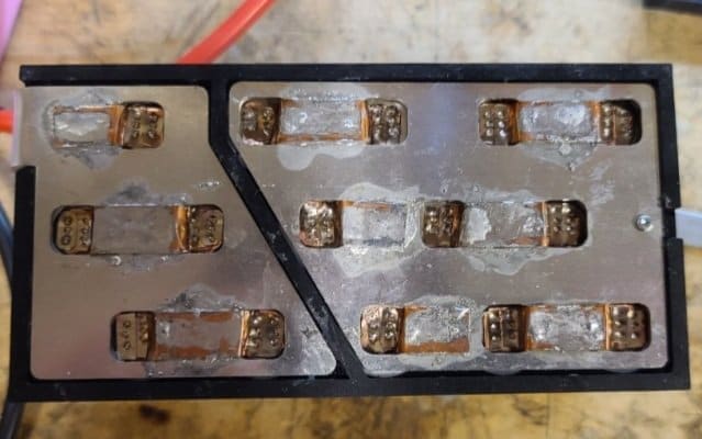
3. Soldered and spot welded
- The priority shifted to making something mechanically robust
- The team had had success with spot welds in the past, but nickel strip couldn't handle the new, higher current
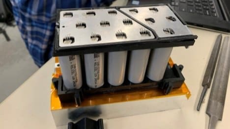
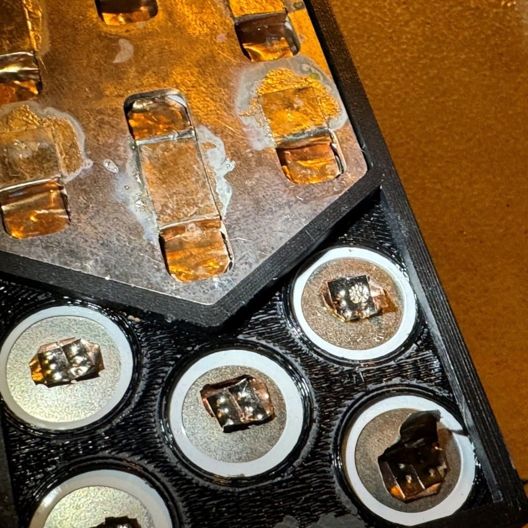
- Decided to use copper strip for its ampacity, and needed a way to connect it to the cells and busbars — used aluminum solder to join the copper to the aluminum
- Spot welded copper to the cells, using two small nickel rectangles as resistors to increase bond strength
- The copper rips before the bonds or solder joints break
- This design was used in the race bike for the rest of the season with no known issues
Cell Testbench
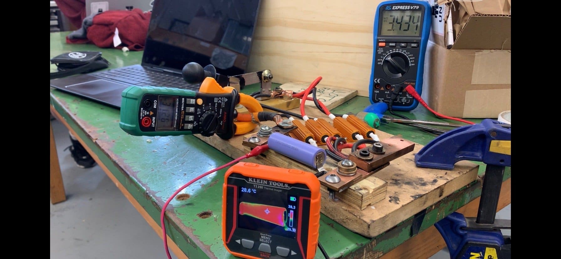
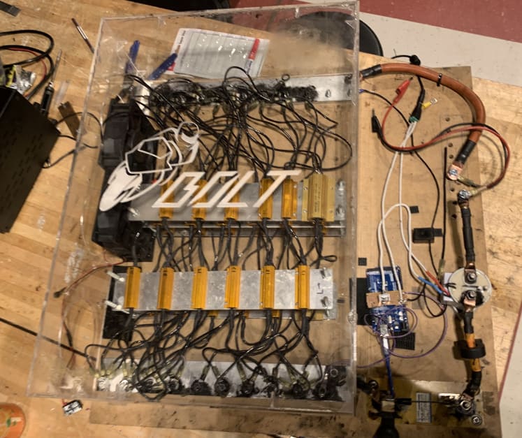
Designed and built a test bench to test battery cells for the electric motorcycle.
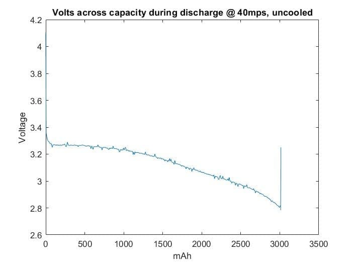
- Drew 250A at 4V (full-throttle equivalent)
- Included an Arduino for data collection — voltage, current, and temperature at different locations
- Wrote a Matlab program to analyze the data
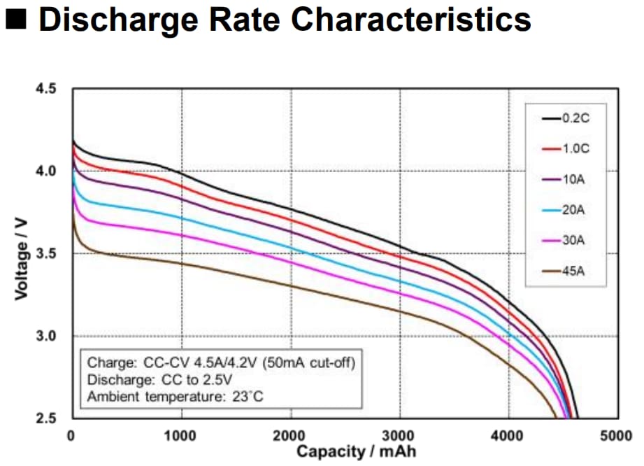
- Was able to test cells against the datasheet's claims
- Used the results to inform battery selection for the motorcycle

Module Testbench
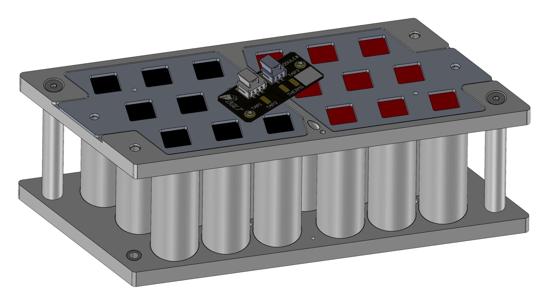
Designed to validate each 5P group within a module.
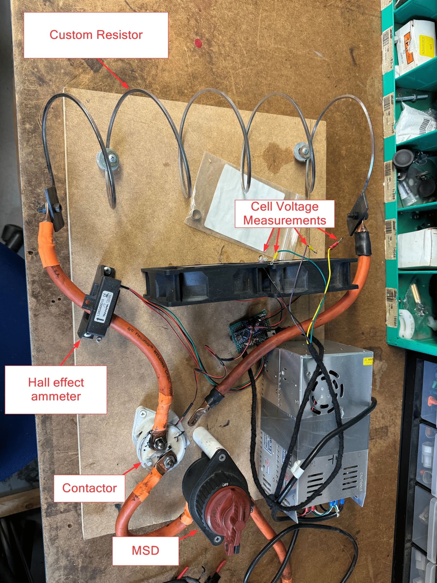
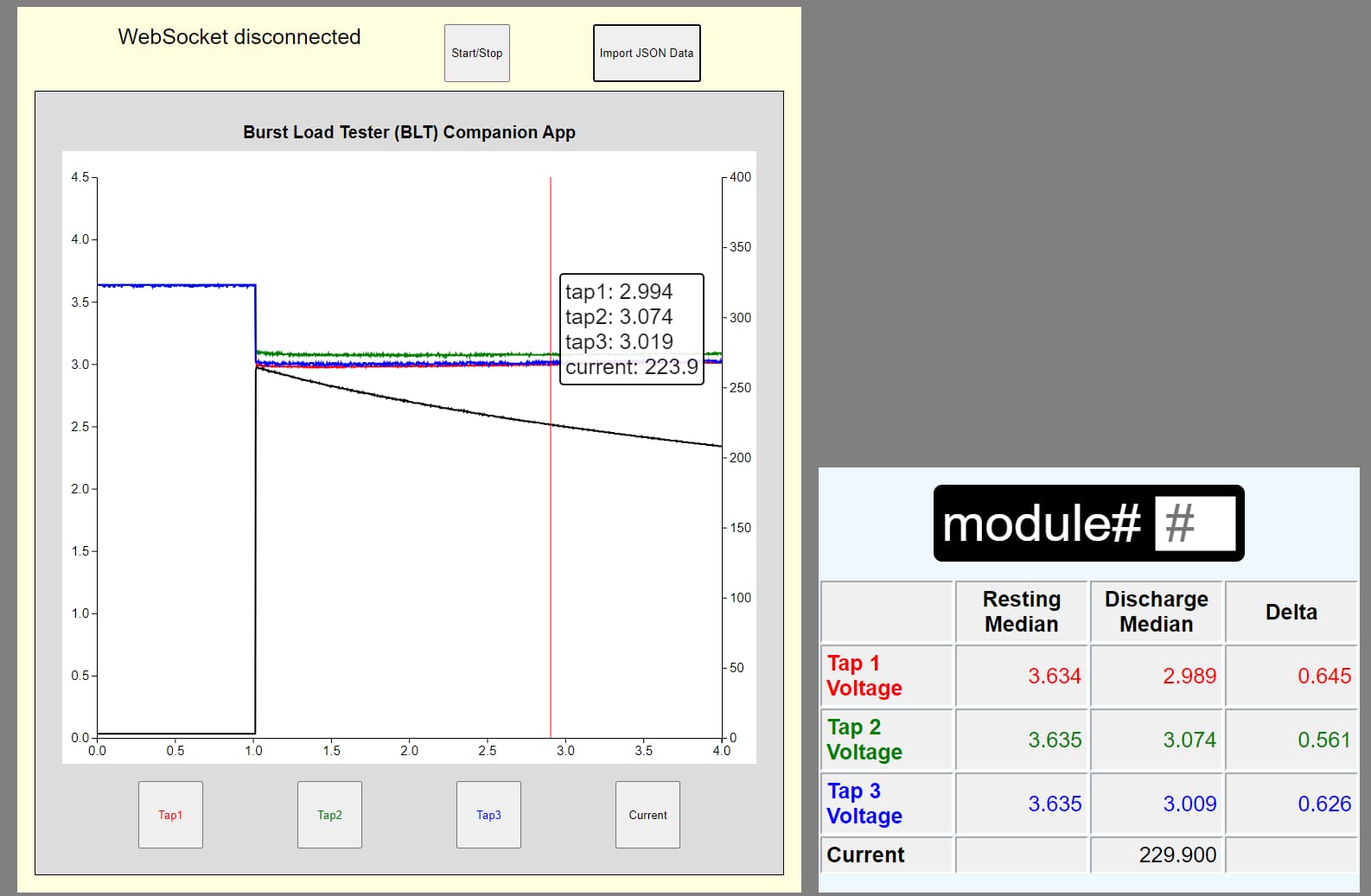
- Drew a 250A burst from the module and measured the voltage drop of each group
- The assumption was that a module with less than 5P (a connection failure) would sag significantly more under load
- Successfully caught 100% of modules with manufacturing errors
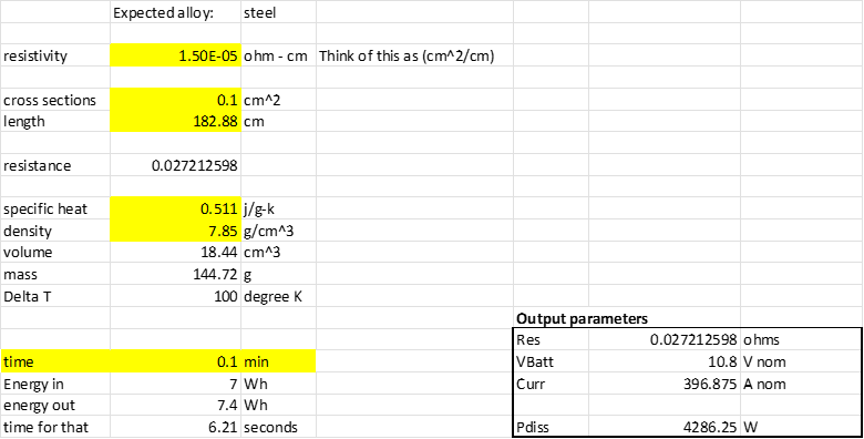
- A resistor bank was cost-prohibitive, so I made a custom resistor out of steel, calculated to be within 20% of target performance at ambient temperature, verified with a 4-wire Kelvin test
- Didn't account for the resistor's resistance change with temperature well enough — combined with voltage sag, this created a current sag in testing
Module PCB
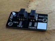
The existing modules were difficult to assemble, relying on voltage tap and thermistor harnesses connected through small bolted joints and ring terminals — a setup prone to failure from vibration.
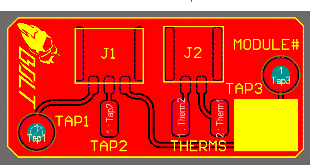
I designed a new interface PCB that permanently attaches to the modules and uses proper connectors for the voltage taps and thermistors instead, designed in Altium with a Solidworks co-designer link.