This project is a work in progress
Electric Moped Project
Goals:
Build an EV with the utility of a moped, but design of a motorcycle
Integrate CAD, FEA, and other engineering skills I have learned through college
Emphasis on DFM, both mechanical and electrical
Enjoy the process and the final product!

The Planning Stage
Design planning
I spent a lot of time looking at mopeds and motorcycles to determine what I wanted to build. I decided that I really liked the modern take on 1970s bikes. Here are some of the images I used as inspiration, and to get an idea of dimensions.
I also decided that I wanted to use a belt drive, mainly to reduce noise. This means that the motor and swingarm need to be coaxial, more about that later.


Design for Manufacturing, Battery
I had 2 main goals for my battery pack; make sure it was not my limiting factor, and avoid unreliable electrical connections like spot welds or wire bonds.
I found some pouch cells that came with a threaded tab before I cam home for the summer, so I was able to test them using the test bench I made for BOLT. Each individual cell is capable of putting out my burst current, and I have 4 in parallel. This means that even if I drew full throttle for the entire lifetime of the pack, it would stay below its temperature limit. This was important to me, as I meant I could seal in the pack without much concern for cooling.
I then designed bolt on busbars (once again laser cut) to make my series and parallel connections between the pack. I originally was going to use copper, but once I realized I couldn’t afford that I switched to aluminum and increased the thickness accordingly.


Design for Manufacturing, Frame
From the beginning I knew I wanted to build this totally ground up, so I could control all the variables. My theory was all the time spent on design would be saved by not needing to take a grinder to an existing frame. This was laughably wrong of course, but I still think it was a good decision, and a good experience!
For the frame, I determined that bent tubes and sheet metal would be the best route. I knew that keeping tight tolerances in tube bending would be difficult. Because of this, I designed my frame to have 3 “geometry defining members” that would fit into themselves and locate everything critical. Then I could get those three outsourced. I could handle the other less critical, and less challenging, tubes myself. This ended up being out of my budget, but I think it was a good idea. The only thing I would change is splitting my top member into two. The near bend makes it be slightly too wide in hindsight. I also used Solidworks FEA to analyze my designs. I am not super confident in the load cases I selected, so I used FEA mostly as a metric to evaluate frame changes, not exactly how it would behave in the real world.
I then designed 2D plates to be ordered from sendcutsend (laser cutting service) that would self locate within the frame geometry. These allowed for a very tightly controlled interface with anything bolting to the frame.


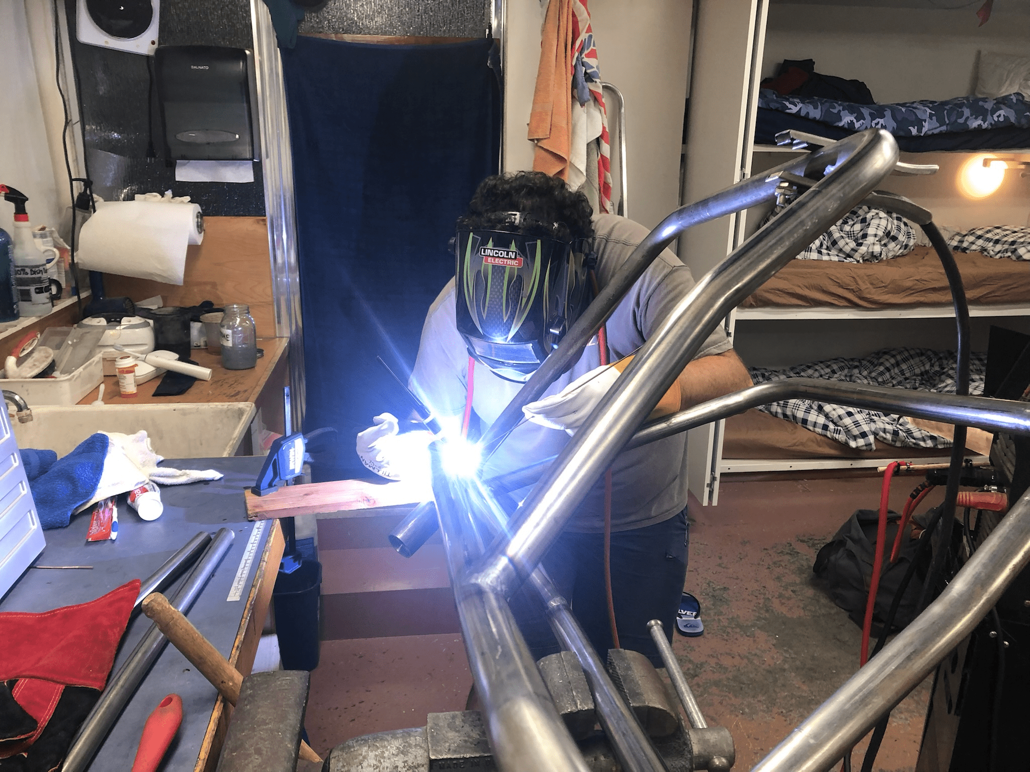
Frame Build
These are photos of my frame build process. It is a slideshow, make sure to click the arrows to see the next photos! Photos are in rough chronological order.

Transferring a SW drawing onto MDF to be cut out. I tried to design the jig to locate the headtube and swingarm axle while allowing welding access.

Bending frame members. It took some practice to get precise bends out of it.

Putting the first bent frame members in the jig.

Second bend put in the bottom bar, test fitting in the full jig with rear datum.

Machining the head tube. I had to machine steps for the thrust bearings.

Coping side members to meet the head tube.

Mounting the head tube in the proper position and angle.

Mounted head tube using tacked on washers.

Close up of tube fit to head tube. I didn't have the proper tool for this so I did it with a little "angle grinder artwork". It wasn't perfect, but close enough I was happy.

Welded first cross member to fit on jig.
After tacking in the jig, I moved to the vice to have better access for full beads.

Test fitting back in the jig after the first welds.

Back in the vice for more welding. Welding the bottom members to the top members now.

Machining notches into a tube to make the swingarm. These notches fit a laser cut plate.

First tacks of the swingarm. Laser cut plates are on the bottom. You can see I was trying to make this piece very precise based on the drawn measurements.

More welds completed on the swing arm.

Test fit of my axle and tensioners. I was overall very happy with how this part turned out.

Turned threaded inserts for the swingarms.

Welded inserts in place. I used big plug welds to handle the shear force this joint is under.

Setting up the jig for the cross members, motor mounts, and swingarm mounts. Because these parts are concentric, they all need to be aligned perfectly.

Swingarm mounts are welded in. Bolt spacer were turned and tacked in place.

Motor fit looked easy in cad, was very tight in real life! I ended up flipping my fasteners to save a little space.

Testing the belt line using a meter stick as a stand in.

Full mock up of the motor and swingarm! I wanted to triple check everything aligned before fully welding in place.